The goal of this project was to design, prototype, and test a drone body that could be fully assembled without tools, while maintaining structural integrity, flight stability, and ease of repair. Using a Cetus FPV drone kit for components, we redesigned the frame, camera mount, motor holders, and battery housing to address the assembly weaknesses of the original. The redesign had to fulfill the following requirements: a single person wearing half-fingered gloves should be able to disassemble the drone without tools. The weight had to be under 250g for regulatory compliance.
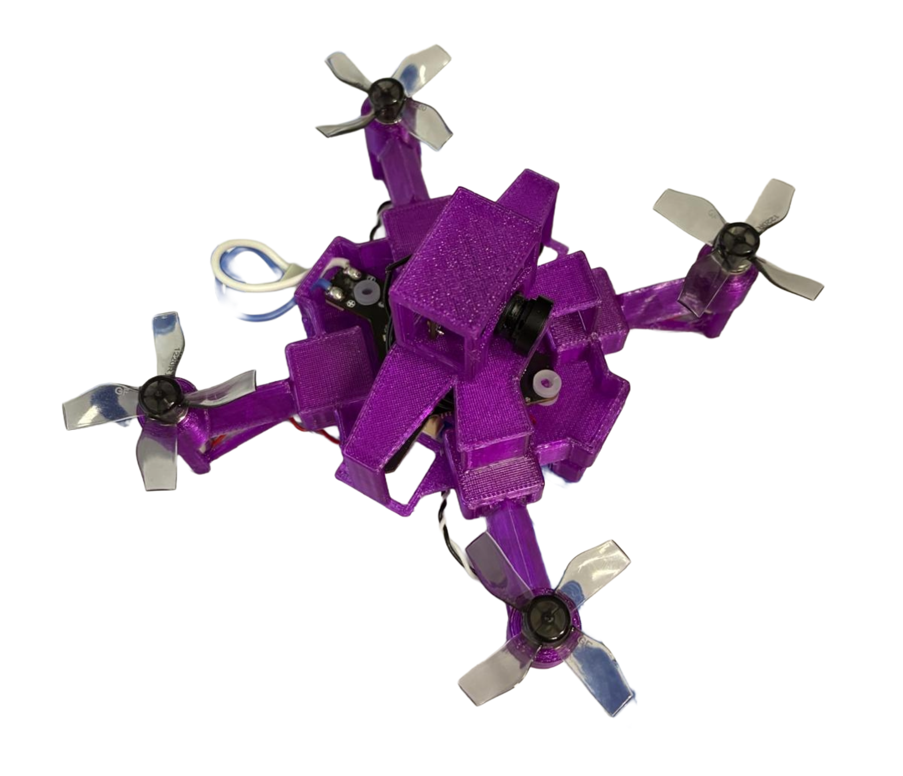
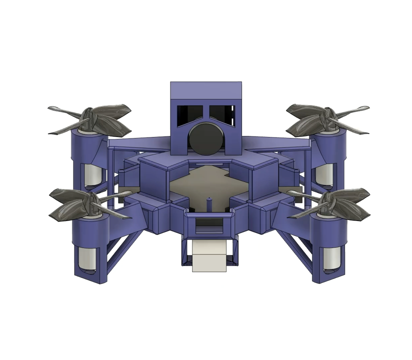
The redesigned drone was printed with PETG. the housing weighed 49.1g, and measured 81×81×47mm. Assembly was fully toolless, and the drone was able to take off, fly in a square, hover, scan a QR code, and land.
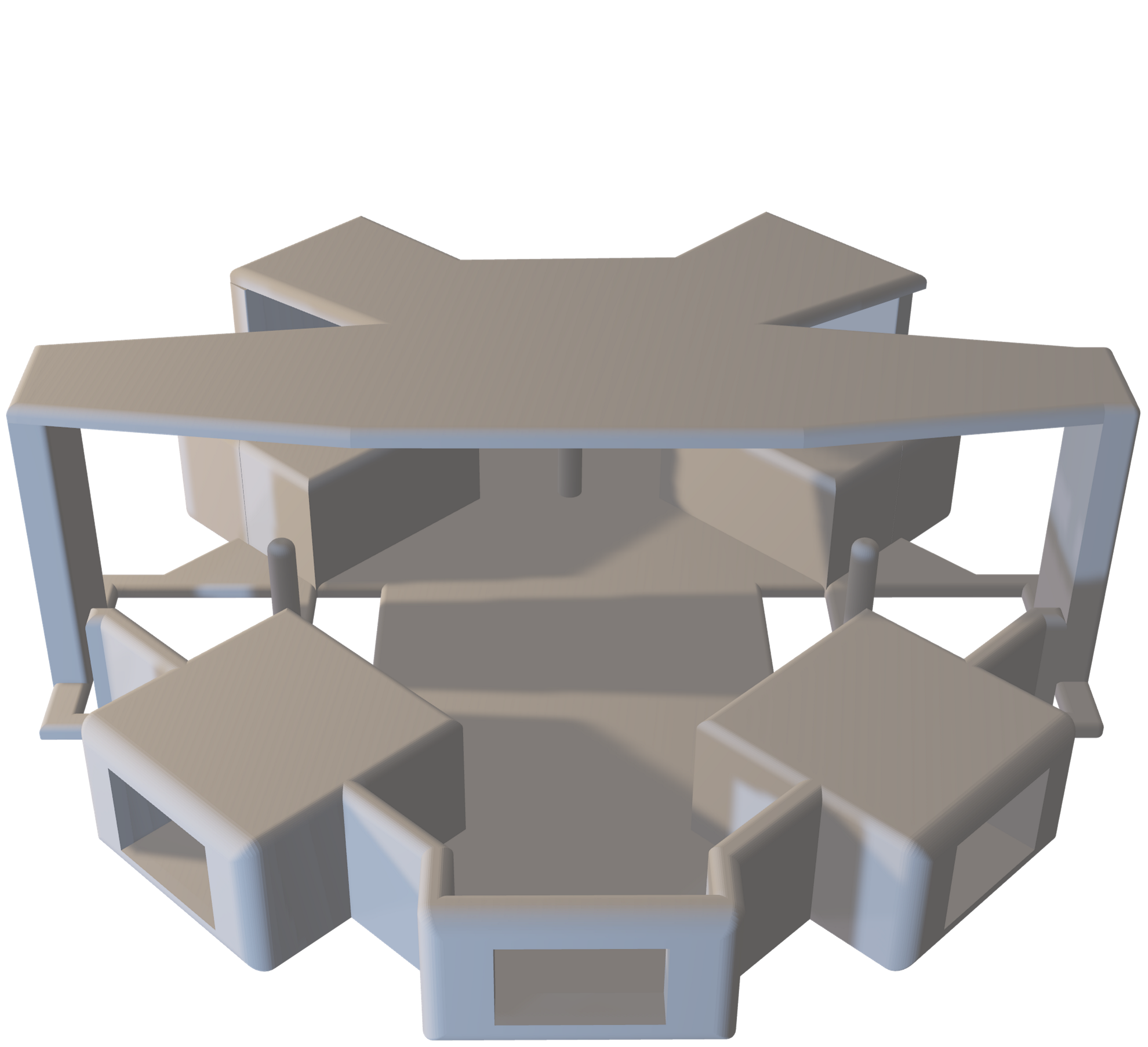
The frame only uses the bare minimum material to maintain structural integrity and allow for all components to be attached. The PCB slides in from above and locks via 4 rods. This replaces the original four screw joinery and cuts swap time from around 2 minutes down to 10 seconds.
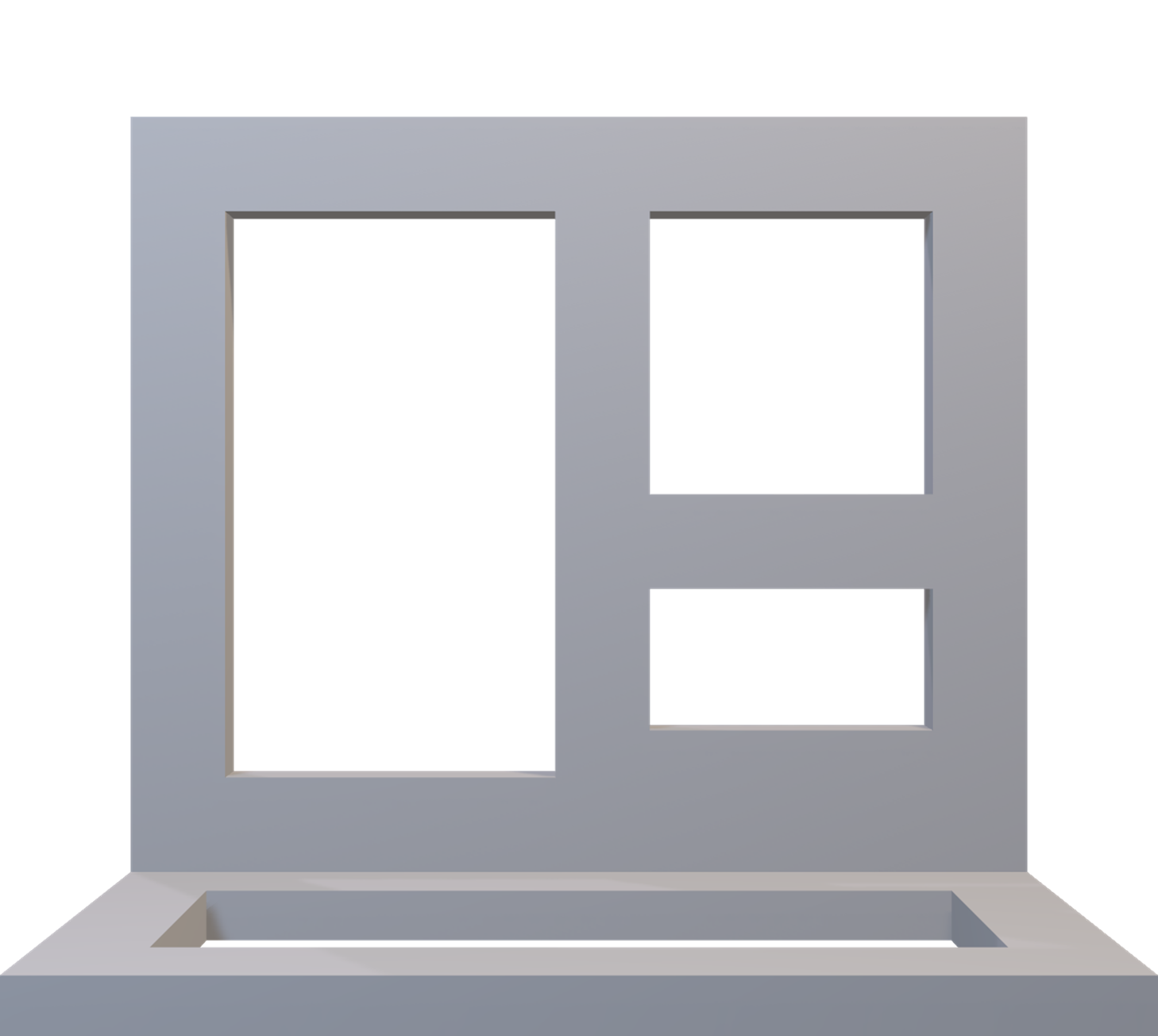
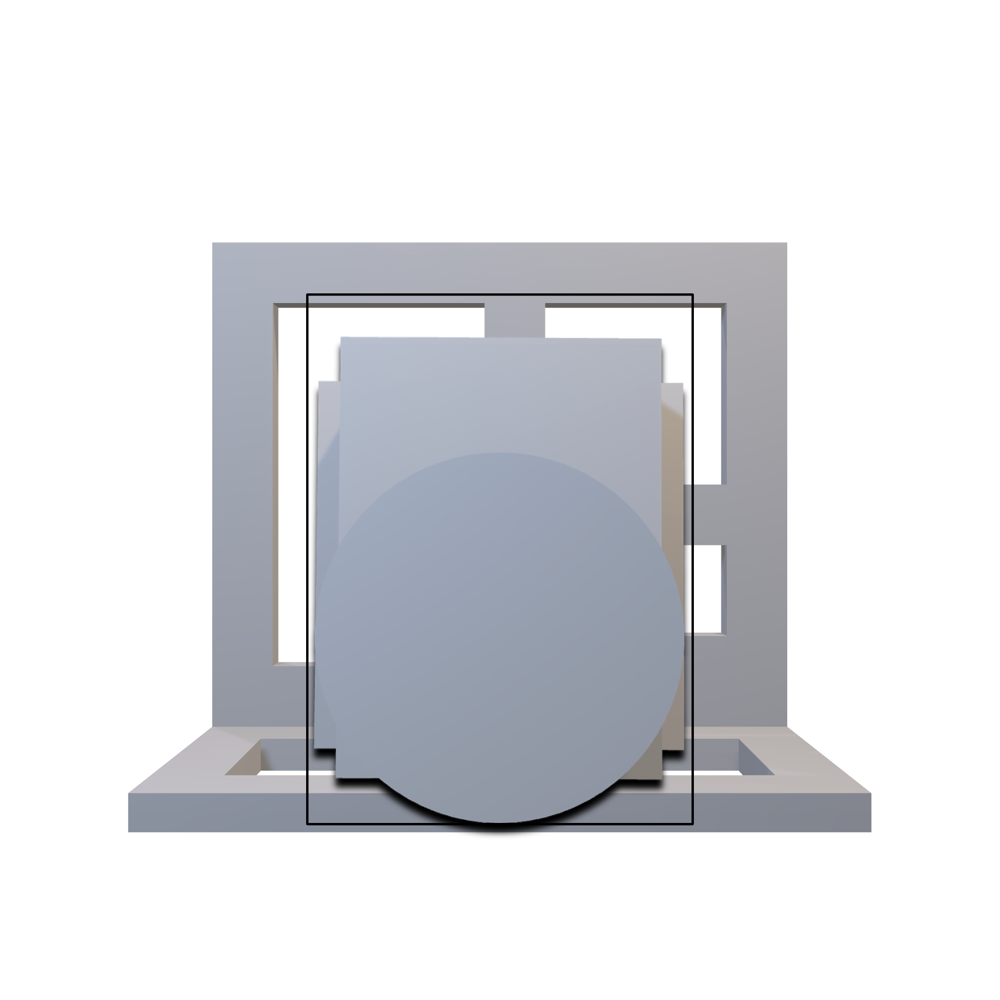
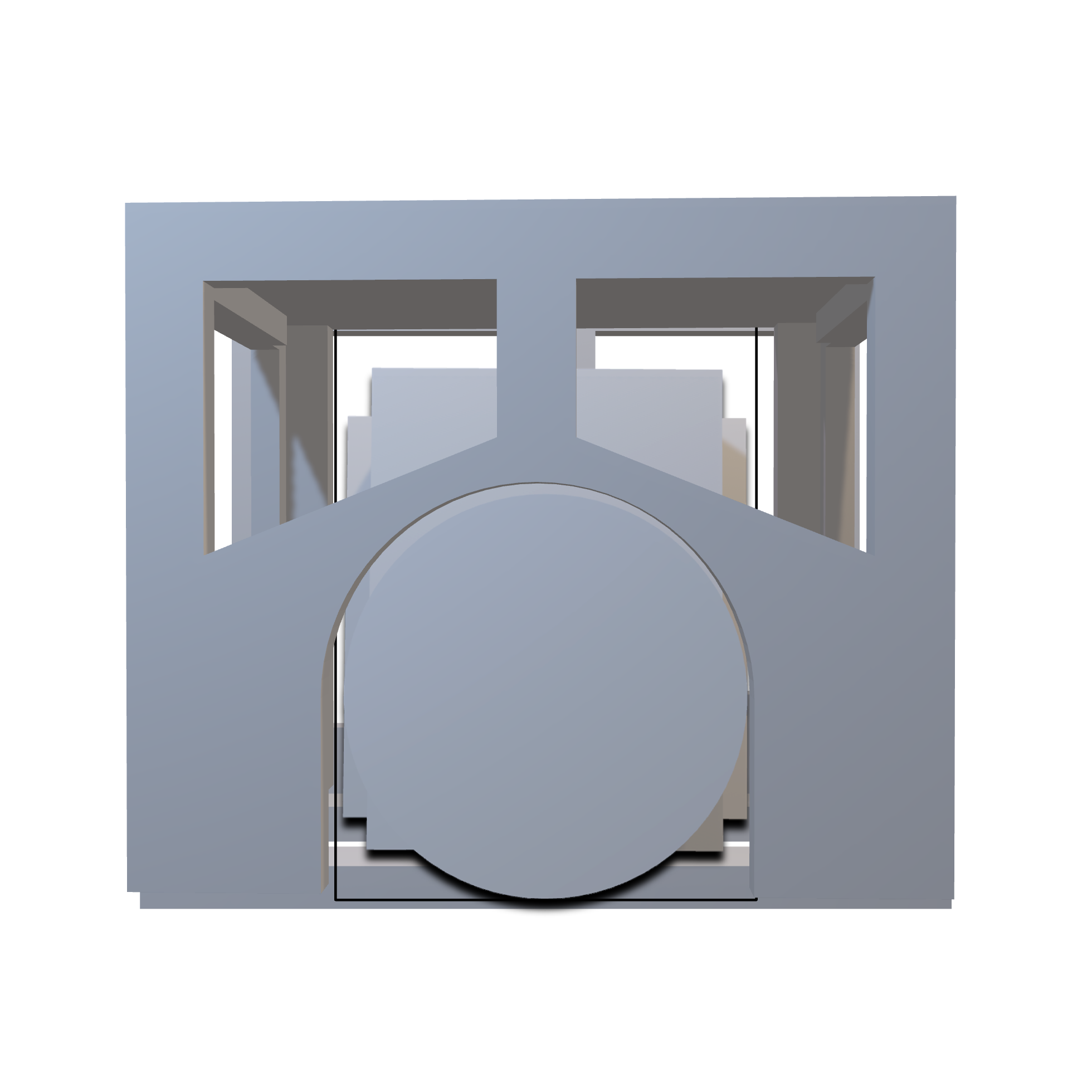
The camera is attached with a housing that clips onto the main body. Material was cut away from all sides to maximise airflow, as the camera tends to overheat during use. Connector slots are built into the housing, so the camera can be easily attached and detached without needing any tools.
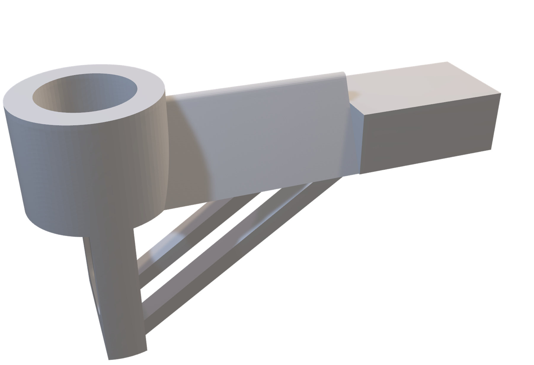
Each motor holder slots into the arm tips of the frame and detaches without tools. The connecting bridge uses a triangular profile to minimise propellor wash. This solved an earlier issue with a rectangular arm that hindered lift. Diagonal supports run from the landing guard up to the bridge to prevent the landing guard from breaking.
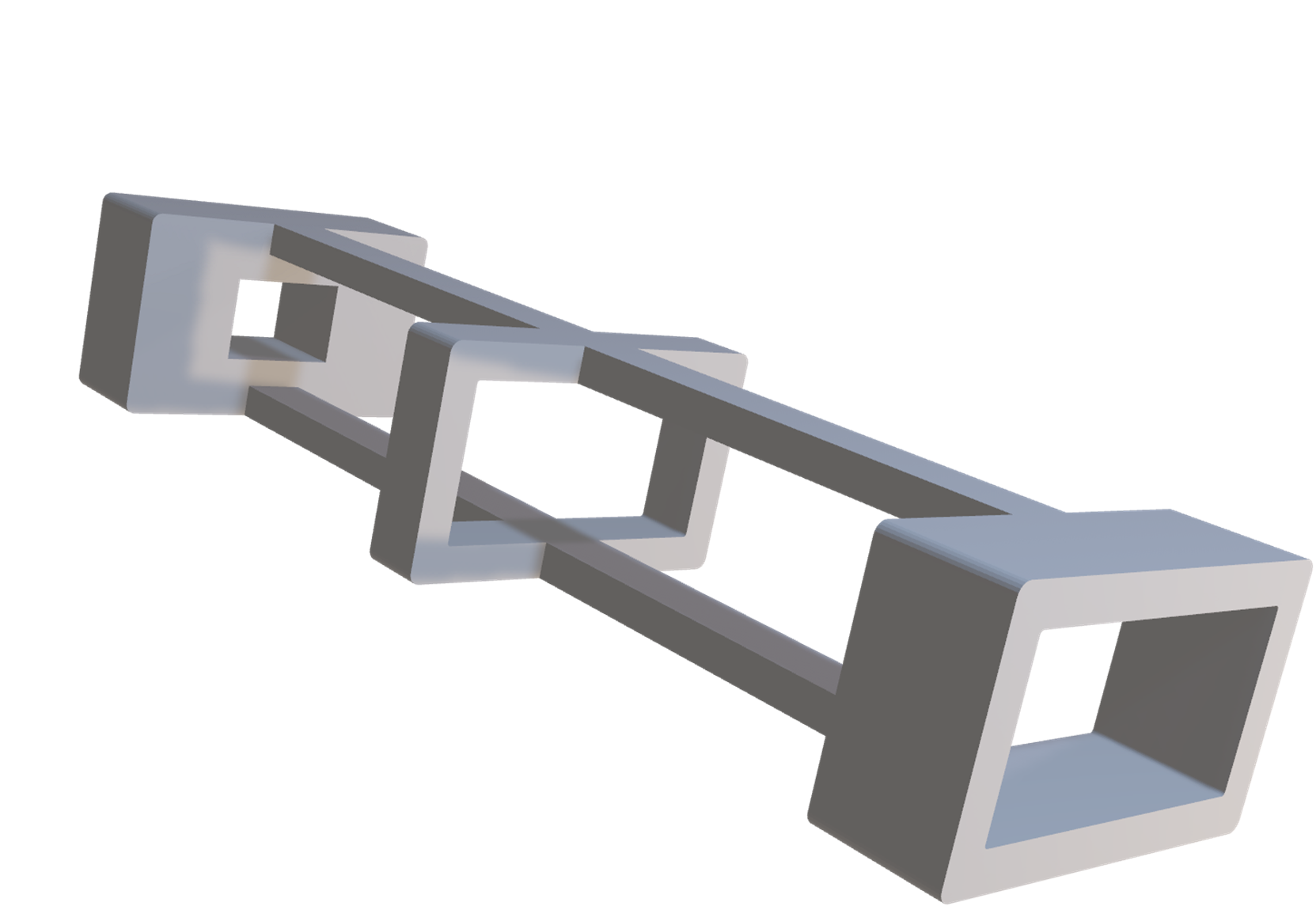
Three rings, one at each end and one in the centre, secure the battery while minimising material and weight. This structure also allows airflow to cool the battery down. The cable connector is pre-positioned so the battery connects automatically when slid into place, with no precise fastening needed.
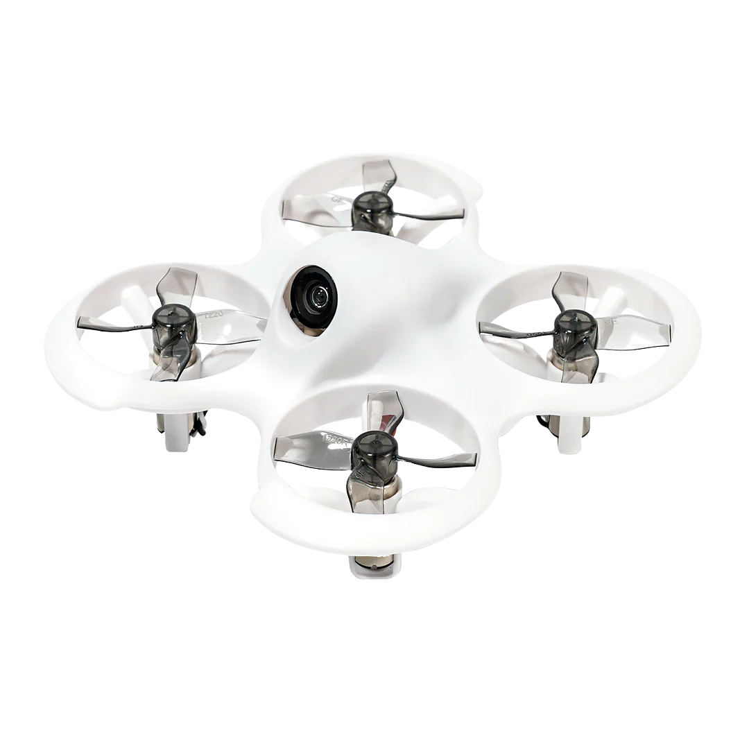 Original Cetus FPV Drone
The original Cetus FPV kit served as the reference design. A teardown and assembly test revealed two fundamental problems that guided the redesign.